
Bau des Lanz HP in Belgien/ Building the Lanz HP in Belgium - Endmontage!
- 2. Mai 2020
- 3 Min. Lesezeit
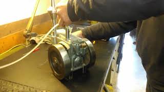
Zapjack hat seinen Lanz HP fertig gebaut, Motor läuft.
Er ist mit dem Ergebnis zufrieden und freut sich auf unser nächstes Projekt - wir übrigens auch :-)
"ZAPJACK" aus Belgien hat mit der Bearbeitung der ersten Teile aus seinem Gußkit begonnen, wir werden auch diesen Bau auf unserer Homepage begleiten.
"ZAPJACK" from Belgium starts machining the first parts from his kit. We will present the complete building at our homepage.


New nice details :o)


Next steps of the frame. Polishing the welding zone.
It’s after finishing that I understand the high importance of all the sizes, angles, …
There is lot of measurement on the gear box, differential, front axle, frame pivot, all angles are so important
Don’t forget, it’s an articulated 4WD type tractor.
This is the reason why I work very carefully and slowly
There are tree secrets to have success: we must measure, measure and measure again
ZAPJACK

Like usual: lot of zero setting before machining.
At first, I’ve machined top side to 9.8mm
After that, same job at the opposite at 9.8mm
Finishing with a reamer 10H7 to have perfect alignment


Käfig für die Zahnräder / Innenteil von den Differentialgehäusen


Differentialgehäuse hinten


Der hintere Achsträger

Vorderes Differentialgehäuse


Achsträger vorne mit montiertem Differentialgehäuse


The next news from Attila, realy nice parts :o)


Machining the piston


maschining the hot bulb

with mounted crankshaft


Finishing the running sleeve


Machining the running sleeve and bore the exhaust duct.


Machining the engine block and the cover.


All the wheels are now finished and with copper rivets only


Der Kurbelwellenbolzen wurde mit +0,01 mm gefertigt und in die temperierten Kurbelwangen eingepresst. Das Pleuellager wurde nicht geteilt (zwei Halbschalen) sondern vor dem Zusammenbau der Kurbelwelle montiert.
Note that there is only +0,01 mm on the axle for fastened in the half-crankshaft
Assembling is by heating
Remark, the bearing of the connecting rod is not split but mounted before assembling


Aktuell befindet sich das Motorpleuel in der Bearbeitung. Weiterhin wurden die verwendeten Messingschrauben für die Felgenmontage als kleiner Fauxpas :o) abgetan und durch Kupfernieten ersetzt. Den verwendeten Nietdrücker gibt es übrigens hier: http://www.ateliermb.ch/
Currently, the engine connecting rod is being machined. Furthermore, the brass screws used for rim mounting were dismantled as small fauxpas :o) and replaced by copper rivets, now it looks beautifuel as it should. The used rivet clamp for mounting you can order here: http://www.ateliermb.ch/


I’m now finished the outside riveting of the wheel
But I will directly paint wheel (inside black), outside (natural) spikes and wheel hub (red)
Rivets and screws (natural)
Screws head must be machined to be half-round
But at first, sand-blasting the separate parts, and assembling after


For the cylinder, I’m waiting for a special ordered end-mill 8mm (half-round)
The bore is finished and close by a plug-in Cast Iron (same quality like cylinder)
This is to prepare the job for the transfer port
Crankshaft: I’ve just started the job
But go from 63mm to 20mm in special allied steel is really a boring job
Especially on my small Schaublin 102


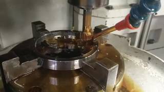
Aufgrund starker Vibrationen habe ich die Zylinderbohrung wie folgt eingebracht: Ich begann mit der Rückseite des Blocks und fertigte den Ø49mm. Dann fertigte ich einen provisorischen Deckel mit einer 20H7 - Bohrung in der Mitte. Danach baute ich mir ein Spindelwerkzeug aus Silberstahl länge 500mm und 20mm Durchmesser. Dann den provisorischen Deckel auf der Rückseite verschrauben und die 20mm Bohrung als Werkzeugführung nutzen. Danach ist der Motorblock kein Problem mehr. Zwei wesentliche Vorteile: Zuerst sind die Zentrierung der Vorderseite und der Rückseite perfekt und beide sind "in-line" Und zweitens keine Vibrationen mehr
I’ve modify the method of bore the block. Due to bad vibrations.
I started by the back side of the block to the finished size of 49mm.
Then, make a temporary cover with a bore of 20H7
After that, I make a tool from a silver-steel axle of 500mm and 20mm diameter.
The temporary cover is fixed on the back side of the block.
After that, bore the block is not more a problem.
Two main advantages:
At first, the centering of the front side and the back side are perfect and both are “in-line”
And at second, no vibrations anymore


Kommentare